Senden und Empfangen per USB an Arduino
-
Hallo,
vor vielen Jahren habe ich mir eine Einbruchmeldeanlage mit einem Arduino gebaut.
Alle Sensoren und Aktoren schön verdrahtet (Funkwellen traue ich irgendwie nicht).
Nun will ich natürlich den Zustand visualisiert darstellen.Zusammen mit meinem hue-System, der Heizungssteuerung und 2 Kameras wird das sicher eine schöne Hausübersicht.
Auf jeden Fall habe ich lange an der Schnittstelle zum Arduino gearbeitet und möchte euch meinen ersten Testaufbau,
der auch funktioniert vorstellen. Vielleicht hilft es jemand.
Die EMA muss ich nur so erweitern, dass je nach Status ein bestimmer Code, im einfachsten Fall ein Byte, gesendet wird. Dann werde ich einen Datenpunkt setzen und visualisieren.
Umgekehrt werde ich den Alarm nicht steuern, ist mir zu unsicher.Hier also der Code für Raspi
/*
Zeigt die grundsätzlichen Funktionen:
Senden und Empfangen von Daten an USB

Ein Arduino Mega2560 sendet per Tastendruck ein "T"
Das Script empfängt das "T", lässt Alexa "Test" sagen und sendet ein "Hi" zurüch an den Arduino

*/
'alexa2.0.Echo-Devices.G091AA080504188V.Commands.speak'/*speak*/// mit putty per ssh Zugriff:
// ls -la /dev/serial/by-id
// um festzustellen wie der Serielle Port heißt

var Serialport = require('serialport');
//var portName = '/dev/ttyUSB0';    //Pi4
var portName = '/dev/ttyACM0';    //PI3

const port = new Serialport(portName, {
    autoOpen: true,
    baudRate: 115200,
	dataBits: 8,
    parity: 'none',
    stopBits: 1,
    flowControl: false
});

// Read the port data
port.on("open", function () {
    console.log('open');
    port.on('data', function(data) {
        console.log(data);
        console.log(data[0]);
        if (data[0] == 84)  {
            console.log("das ist ein T");
            setState('alexa2.0.Echo-Devices.G091AA080504188V.Commands.speak', "Test");
            port.write('Hi!');
        }
        if (data[0] == 66)  {console.log("das ist ein B"); }  // Tue was anderes
    });
});
und Arduino
// IMPORTANT: ELEGOO_TFTLCD LIBRARY MUST BE SPECIFICALLY
// CONFIGURED FOR EITHER THE TFT SHIELD OR THE BREAKOUT BOARD.
// SEE RELEVANT COMMENTS IN Elegoo_TFTLCD.h FOR SETUP.
//Technical support:goodtft@163.com

#include <Elegoo_GFX.h>    // Core graphics library
#include <Elegoo_TFTLCD.h> // Hardware-specific library

// The control pins for the LCD can be assigned to any digital or
// analog pins...but we'll use the analog pins as this allows us to
// double up the pins with the touch screen (see the TFT paint example).
#define LCD_CS A3 // Chip Select goes to Analog 3
#define LCD_CD A2 // Command/Data goes to Analog 2
#define LCD_WR A1 // LCD Write goes to Analog 1
#define LCD_RD A0 // LCD Read goes to Analog 0

#define LCD_RESET A4 // Can alternately just connect to Arduino's reset pin

// When using the BREAKOUT BOARD only, use these 8 data lines to the LCD:
// For the Arduino Uno, Duemilanove, Diecimila, etc.:
//   D0 connects to digital pin 8  (Notice these are
//   D1 connects to digital pin 9   NOT in order!)
//   D2 connects to digital pin 2
//   D3 connects to digital pin 3
//   D4 connects to digital pin 4
//   D5 connects to digital pin 5
//   D6 connects to digital pin 6
//   D7 connects to digital pin 7
// For the Arduino Mega, use digital pins 22 through 29
// (on the 2-row header at the end of the board).

// Assign human-readable names to some common 16-bit color values:
#define	BLACK   0x0000
#define	BLUE    0x001F
#define	RED     0xF800
#define	GREEN   0x07E0
#define CYAN    0x07FF
#define MAGENTA 0xF81F
#define YELLOW  0xFFE0
#define WHITE   0xFFFF

Elegoo_TFTLCD tft(LCD_CS, LCD_CD, LCD_WR, LCD_RD, LCD_RESET);
// If using the shield, all control and data lines are fixed, and
// a simpler declaration can optionally be used:
// Elegoo_TFTLCD tft;

int zeilen = 0;
int spalten = 0;

void setup(void) {
  Serial.begin(115200);
  Serial.println(F("TFT LCD test"));

#ifdef USE_Elegoo_SHIELD_PINOUT
  Serial.println(F("Using Elegoo 2.4\" TFT Arduino Shield Pinout"));
#else
  Serial.println(F("Using Elegoo 2.4\" TFT Breakout Board Pinout"));
#endif

  Serial.print("TFT size is "); Serial.print(tft.width()); Serial.print("x"); Serial.println(tft.height());

  tft.reset();

  uint16_t identifier = tft.readID();
  if (identifier == 0x9325) {
    Serial.println(F("Found ILI9325 LCD driver"));
  } else if (identifier == 0x9328) {
    Serial.println(F("Found ILI9328 LCD driver"));
  } else if (identifier == 0x4535) {
    Serial.println(F("Found LGDP4535 LCD driver"));
  } else if (identifier == 0x7575) {
    Serial.println(F("Found HX8347G LCD driver"));
  } else if (identifier == 0x9341) {
    Serial.println(F("Found ILI9341 LCD driver"));
  } else if (identifier == 0x8357) {
    Serial.println(F("Found HX8357D LCD driver"));
  } else if (identifier == 0x0101)
  {
    identifier = 0x9341;
    Serial.println(F("Found 0x9341 LCD driver"));
  }
  else if (identifier == 0x1111)
  {
    identifier = 0x9328;
    Serial.println(F("Found 0x9328 LCD driver"));
  }
  else {
    Serial.print(F("Unknown LCD driver chip: "));
    Serial.println(identifier, HEX);
    Serial.println(F("If using the Elegoo 2.8\" TFT Arduino shield, the line:"));
    Serial.println(F("  #define USE_Elegoo_SHIELD_PINOUT"));
    Serial.println(F("should appear in the library header (Elegoo_TFT.h)."));
    Serial.println(F("If using the breakout board, it should NOT be #defined!"));
    Serial.println(F("Also if using the breakout, double-check that all wiring"));
    Serial.println(F("matches the tutorial."));
    identifier = 0x9328;

  }
  tft.begin(identifier);
  tft.fillScreen(BLACK);
  tft.setTextColor(GREEN); tft.setTextSize(2);
  tft.setCursor(0, 0);

  pinMode(50, INPUT_PULLUP); //Taster
}


void loop(void) {

  if (Serial.available() > 0) {
    char zeichen = Serial.read();
    if (zeichen == 10) {
      tft.println();
      zeilen++;
    }
    else {
      tft.print(zeichen);
      spalten++;
    }
    if (spalten == 15) {
      spalten = 0;
      tft.println();
      zeilen++;
    }
    if (zeilen > 15) {
      zeilen = 0;
      tft.fillScreen(BLACK);
      tft.setTextColor(GREEN); tft.setTextSize(2);
      tft.setCursor(0, 0);
    }
  }
  if (digitalRead(50) == LOW){
    Serial.println("T");
    delay(10);
    while(digitalRead(50) == LOW);
    delay(10);
  }
}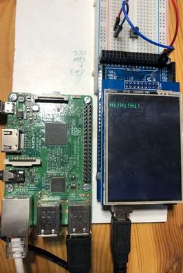
Würde mich interessieren, ob jemand was Ähnliches gemacht hat.
